")
")
")

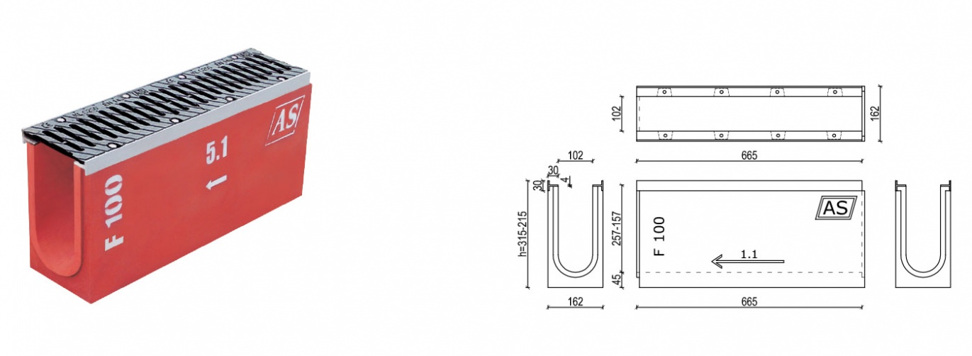
AS-100
AS-100 CHANNELS
CE designation- Standard PN-EN 1433:2005
Declaration of Conformity
Hygienic Certificate HK/B/0786/01/2011
Catalogue No A.I.
| A.I. | Part No. | Channels AS-100 | Width [mm] | Height [mm] | Length [mm] | Cross-section [cm2] | Inlet surface [cm2/mb] | Weight [kg] | Cast iron grates |
|---|---|---|---|---|---|---|---|---|---|
| A.I.1. | 1-25 | with slope 0,6% | 162 | 315 - 215 | 665 | 251-149 | 434 | 39.9-30.8 | |
| A.I.2. | 1.1 | with no slope | 162 | 315 | 665 | 251 | 434 | 39.9 | |
| A.I.3. | 5.1 | with no slope | 162 | 295 | 665 | 231 | 434 | 38.3 | |
| A.I.4. | 10.1 | with no slope | 162 | 275 | 665 | 210 | 434 | 37.3 | |
| A.I.5. | 15.1 | with no slope | 162 | 255 | 665 | 190 | 434 | 35.3 | |
| A.I.6. | 20.1 | with no slope | 162 | 235 | 665 | 169 | 434 | 32.4 | |
| A.I.7. | 25.1 | with no slope | 162 | 215 | 665 | 149 | 434 | 30.8 | |
| A.I.8. | 25.1A | connecting No. 25.1 with AS-B100 | 162 | 215 | 665 | 149 | 434 | 31.5 | |
| A.I.9. | 0.1.1 | upper part of a basin | 162 | 315 | 665 | 251/475* | 434 | 32.7 | |
| A.I.10. | 0.5.1 | upper part of a basin | 162 | 295 | 665 | 231/475* | 434 | 31.1 | |
| A.I.11. | 0.10.1 | upper part of a basin | 162 | 275 | 665 | 210/475* | 434 | 30.1 | |
| A.I.12. | 0.15.1 | upper part of a basin | 162 | 255 | 665 | 190/475* | 434 | 28.1 | kl.B125-3.0kg |
| A.I.13. | 0.20.1 | upper part of a basin | 162 | 235 | 665 | 169/475* | 434 | 25.2 | kl.C250-3.4kg |
| A.I.14. | 0.25.1 | upper part of a basin | 162 | 215 | 665 | 149/475* | 434 | 23.6 | kl.D400-4.4kg |
| A.I.15. | - | cover with an outlet pipe to the No. 1.1 | 162 | 315 | - | - | - | 2.8 | kl.E600-4.8kg |
| A.I.16. | - | cover with an outlet pipe to the No. 5.1 | 162 | 295 | - | - | - | 2.4 | kl.F900-6.2kg |
| A.I.17. | - | cover with an outlet pipe to the No. 10.1 | 162 | 275 | - | - | - | 2.0 | |
| A.I.18. | - | cover with an outlet pipe to the No. 15.1 | 162 | 255 | - | - | - | 1.6 | |
| A.I.19. | - | cover with an outlet pipe to the No. 20.1 | 162 | 235 | - | - | - | 1.2 | |
| A.I.20. | - | cover with an outlet pipe to the No. 25.1 | 162 | 215 | - | - | - | 0.8 | |
| A.I.21. | - | blind cover to No. 1.1 | 162 | 315 | - | - | - | 4.0 | |
| A.I.22. | - | blind cover to No. 5.1 | 162 | 295 | - | - | - | 3.6 | |
| A.I.23. | - | blind cover to No. 10.1 | 162 | 275 | - | - | - | 3.2 | |
| A.I.24. | - | blind cover to No. 15.1 | 162 | 255 | - | - | - | 2.8 | |
| A.I.25. | - | blind cover to No. 20.1 | 162 | 235 | - | - | - | 2.4 | |
| A.I.26. | - | blind cover to No. 25.1 | 162 | 215 | - | - | - | 2.0 |
BASIN ELEMENTS
| A.V. | Part No. | BASIN ELEMENTS | Width [mm] | Height [mm] | Length [mm] | Weight [kg] |
|---|---|---|---|---|---|---|
| A.V.1. | A | transient element without outlet | 162 | 320 | 680 | 38.4 |
| A.V.2. | A | transient element with front outlet | 162 | 320 | 680 | 37.3 |
| A.V.3. | A | transient element with front outlet | 162 | 320 | 680 | 37.0 |
| A.V.4. | B | element with bottom without outlet | 162 | 330 | 680 | 49.9 |
| A.V.5. | B | element with bottom with side outlet | 162 | 330 | 680 | 48.8 |
| A.V.6. | B | element with bottom with front outlet | 162 | 330 | 680 | 48.5 |
| A.V.7. | - | dirt bucket | 80 | 250 | 400 | 3.0 |
Specification
{slider 1. Intended use – place of application}
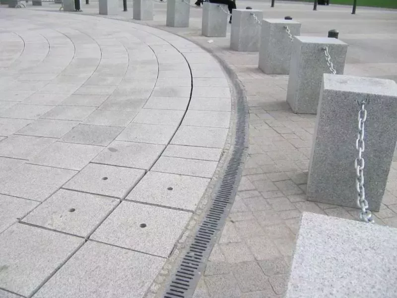
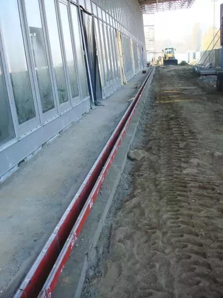
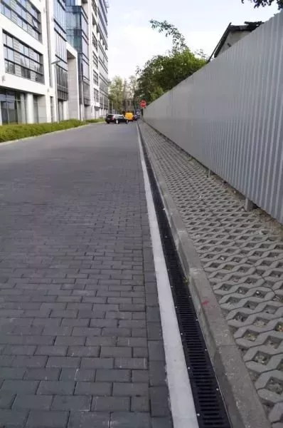
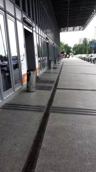
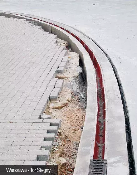
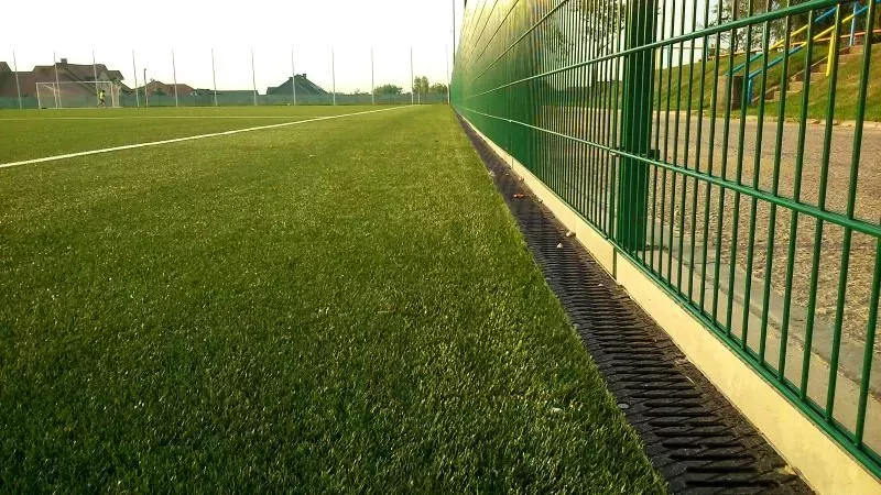
draining roads, streets, garages, car parks, entrances, petrol stations, car washes, etc.
{slider 2. Technological capabilities}
- parts with a 0.6% internal slope
- parts with no internal slope
- possibility to connect parts at some angle
- basins with thrash boxes, covers with a stub pipe, blanking-off covers,
- bodies with holes in the bottom or in the side walls – to drain water
- marking and numbering facilitates to assemble the parts into appropriate systems
{slider 3. Technical information}
Dimensions:
- length: 665 mm
- external width: 162mm
- internal width: 102 mm
- height: from 315 mm to 215 mm (internal slope 0.6%)
- h= 315; 295, 275, 255, 235 and 215mm, (internal slope 0%)
THE CHANNEL BODY is made of concrete in the C55/67 strength class with polymer additives and reinforced with alcali – resistant glass fibre. This concrete improves the properties of the channel and makes it more resistant to bending and hitting. This concrete is also resistant as well as to long – lasting exposure to frost and defrosting salts ("+R").
THE BODY WALLS are protected with a coloured impregnation which limits water vaporization at the concrete curing time and protects the channel against environmental aggressiveness. The impregnation increases also adhesiveness of the external wall to the concrete housing. Applying the coloured impregnation makes it easier to control if protection has been made correctly. The channel bodies are finished with “male” and “female” cut outs enabling to provide tight connection of AS drainage system elements.
SUPPORTING SLATS are made of hot-dip galvanized rolled steel and are fixed to the body walls. These slats protect the channel edges and constitute solid element to fasten the grates.
GRATES – made of cast iron – painted or coated with KTL - in the classes from B125 kN to F900 kN.
GRATE FIXING – with stainless bolts, screwed into galvanized , threaded seats made in the supporting slats. The fixing seats are through – adapted for cleaning.
SETTING THE CHANNELS – on a concrete strip footing with a lateral concrete encasement.
CONNECTING CHANNELS – applying frost and water resistant mortars.
{slider 4. Quality, workmanship precision, and others}
This very simple and safe to install and apply product, entirely fabricated of Polish materials by a domestic company is of very high quality.
The top product quality is assured by AS PPH A. Sobiesiak due to applying "High Strength Concrete" and materials protected permanently against corrosion.
The guarantee of the top quality is the ISO 9001:2008 certificate, too.
{slider 5. Safety}
Applying AS drainage system does not cause any safety risk when installing it, however the general regulations of occupational safety and health for Construction and Installation works should be followed. Due to a solid grate fastening, the AS drainage systems are absolutely safe when utilizing the pavement.
Drainage of the pavement with the AS system and with simultaneous observance of the designing guidelines and installation instructions will enable to avoid troublesome breakdowns and a building degrading, and the maintenance will be limited to cleaning the channels once a year.
{/sliders}
Photo